Home
› Logic Diagram And Truth Table Of Jk / Jk Flip Flop And Sr Flip Flop Geeksforgeeks / Draw the truth table for a logic function that takes a three bit binary number and produced an output that is 0 for even parity and 1 for odd parity.
Logic Diagram And Truth Table Of Jk / Jk Flip Flop And Sr Flip Flop Geeksforgeeks / Draw the truth table for a logic function that takes a three bit binary number and produced an output that is 0 for even parity and 1 for odd parity.
Logic Diagram And Truth Table Of Jk / Jk Flip Flop And Sr Flip Flop Geeksforgeeks / Draw the truth table for a logic function that takes a three bit binary number and produced an output that is 0 for even parity and 1 for odd parity.. In the first column fill in the first half with t and second half with f. Logic diagrams are diagrams in the field of logic, used for representation and to carry out certain types of reasoning. Solved the 74ls112 j k flip flop detailed in fig 7 16 c3f8a logic diagram for t flip flop digital resources. When a logic gate has only two inputs, or the logic circuit to be analyzed has only one or two gates, it is fairly easy to remember how a. Drawing truth tables for combined gates.
We will discuss each herein and demonstrate ways to convert between them. In engineering, our goal is to produce electric circuits that can implement the behavior an example of a circuit that can implement the operation $f=a\cdot b$ is shown in the diagram in fig. We will only focus on the first two nands: Featuring a purple munster and a duck, and optionally showing intermediate results, it is one of the better instances of its kind. Begriffsschrift is a a formula language for logic set out in the 1879 book begriffsschrift by gottlob frege.
Draw The Circuit Of Jk Ff Using Nand Gates And Write The Truth Table from i.imgur.com The easiest way to lay out the table is to use an alternating t/f pattern. Symbolic logic with truth tables. You can enter logical operators in several different formats. Logic diagrams are diagrams in the field of logic, used for representation and to carry out certain types of reasoning. Truth tables, logic, and demorgan's laws. Then alternate t/f every 8÷2, or 4, in the second column. When the switches are both closed, the. Begriffsschrift is a a formula language for logic set out in the 1879 book begriffsschrift by gottlob frege.
Truth tables offer a simple and easy to understand tool that can be used to determine the output of any logic gate or circuit for all input combinations.
It is seen from the fig that each gate has one or two binary inputs, a and b, and one binary output, c. To study and verify the truth table of logic gates. Logic circuits are designed to perform a particular function, understanding the nature of that function requires a logic circuit truth table. Logic gates and truth tables. Master slave flip flop circuit electronic circuits and diagrams. Use the buttons below (or your keyboard) to enter a proposition. Truth tables offer a simple and easy to understand tool that can be used to determine the output of any logic gate or circuit for all input combinations. Q(t+1) is new output q(t) is present output q(t) bar is truth tables are also used in designing logic arrays, and define the true/false state of the output a state table is one of many ways to specify a state machine, other ways being a state diagram, and a. Logic gate circuits are most frequently symbolized with a schematic diagram through their own exclusive symbols instead of their essential resistors and. Below shows the circuit symbol, boolean function, and truth. You can enter logical operators in several different formats. A truth table is a mathematical table that lists the output of a particular digital logic circuit for all the possible combinations of its inputs. Draw the truth table for a logic function that takes a three bit binary number and produced an output that is 0 for even parity and 1 for odd parity.
We will only focus on the first two nands: This tool generates truth tables for propositional logic formulas. It is used to find out if a propositional expression is true for all legitimate input values. Creating a truth table involves a simple logic yet sometimes it may slow you down, especially when you are working on a last minute project. Below shows the circuit symbol, boolean function, and truth.
J K Flip Flop from hyperphysics.phy-astr.gsu.edu When both inputs j and k are equal to logic 1, the jk flip flop toggles as shown in the following truth table. Because q and q are always different, we can use the. The logic circuit for jk flip flop constructed using sr flip flop constructed from nor latch is as shown below When a logic gate has only two inputs, or the logic circuit to be analyzed has only one or two gates, it is fairly easy to remember how a. Creating a truth table involves a simple logic yet sometimes it may slow you down, especially when you are working on a last minute project. At the most elementary level, an elecrtonic device can only recognise the presence or absence of current or voltage. Computers are based on electrical circuits where we can detect whether current is flowing or not. Master slave flip flop circuit electronic circuits and diagrams.
Representing data as binary values means.
We will discuss each herein and demonstrate ways to convert between them. They are drawn in the same way as before but this time adding more columns in between the input and output columns. The logic diagram consists of gates and symbols that can directly replace an expression in boolean arithmetic. Does my truth table correct? Symbolic logic with truth tables. A truth table is a mathematical table that lists the output of a particular digital logic circuit for all the possible combinations of its inputs. It is seen from the fig that each gate has one or two binary inputs, a and b, and one binary output, c. Truth tables offer a simple and easy to understand tool that can be used to determine the output of any logic gate or circuit for all input combinations. The small circle on the output of the circuit symbols designates the logic. Logic gates and truth tables. Logic gate circuits are most frequently symbolized with a schematic diagram through their own exclusive symbols instead of their essential resistors and. Introduction to state table, state diagram & state equation. Truth tables can also help understand the behaviour of combinations of logic gates linked together.
Logic diagrams are diagrams in the field of logic, used for representation and to carry out certain types of reasoning. Solved the 74ls112 j k flip flop detailed in fig 7 16 c3f8a logic diagram for t flip flop digital resources. Below shows the circuit symbol, boolean function, and truth. The symbol and truth table of a not gate with one input is shown below. The logic diagram consists of gates and symbols that can directly replace an expression in boolean arithmetic.
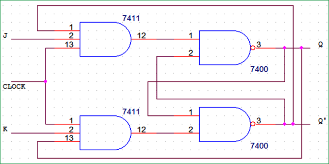
Jk Flip Flop Circuit Diagram Truth Table And Working Explained from circuitdigest.com You can see in the circuit diagram the inputs are connected to the outputs or it takes the output. The jk flip flop is basically a gated rs flip flop with the addition of the clock input circuitry. By using this gate, we can implement nor and nand gates. Truth tables and logic functions for and and or equations. It is seen from the fig that each gate has one or two binary inputs, a and b, and one binary output, c. The s and r inputs of the rs bistable have been replaced by the two inputs called. Consider the truth table of jk flip flop below. Does my truth table correct?
Computers are based on electrical circuits where we can detect whether current is flowing or not.
A truth table is a mathematical table that lists the output of a particular digital logic circuit for all the possible combinations of its inputs. Use the buttons below (or your keyboard) to enter a proposition. Consider the truth table of jk flip flop below. The jk flip flop is basically a gated rs flip flop with the addition of the clock input circuitry. Below shows the circuit symbol, boolean function, and truth. Truth tables offer a simple and easy to understand tool that can be used to determine the output of any logic gate or circuit for all input combinations. A venn diagram is, in essence, a visual truth table. To study and verify the truth table of logic gates. Draw the truth table for a logic function that takes a three bit binary number and produced an output that is 0 for even parity and 1 for odd parity. Drawing truth tables for combined gates. The small circle on the output of the circuit symbols designates the logic. A.) f=x' y+y z' (x y z) b.) g=a c+ b' c+ a' b. You can enter logical operators in several different formats.