Home
› 6 Pin Wire Diagram : Brevet 6 Pin Power Window Switch Wiring Diagram - According to wiring diagram change 6 pin din plug to usb, you will find only four wires used in the cable.typically it uses black, green, red and white wire colours.
6 Pin Wire Diagram : Brevet 6 Pin Power Window Switch Wiring Diagram - According to wiring diagram change 6 pin din plug to usb, you will find only four wires used in the cable.typically it uses black, green, red and white wire colours.
6 Pin Wire Diagram : Brevet 6 Pin Power Window Switch Wiring Diagram - According to wiring diagram change 6 pin din plug to usb, you will find only four wires used in the cable.typically it uses black, green, red and white wire colours.. Each part should be set and linked to different parts in particular manner. Start date sep 21, 2018. To do this, a wiring diagram for the equipment is essential. 4 pin trailer wiring diagram. 6 pin cdi.conection and wiring diagram.(tagalog tutorial) part 3.
Rj45 wiring pinout for crossover and straight through lan ethernet network cables. Ethernet cable pin outs align the colored wires according to the wiring diagrams above. It shows the components of the circuit as simplified shapes, and the knack and signal links amongst the devices. Black cable serves as floor, exactly like in every other device. Connect leads as shown per your service part number.
Kpc9612 Wiring Diagram 6 Pin Din from schematron.org A wiring diagram is an easy visual representation in the physical connections and physical layout of an electrical system or circuit. Connect leads as shown per your service part number. Cut and strip (ground) black wire pin 24 and (+12v) yellow wire pin 11. Pinout diagrams and wire colours for cat 5e, cat 6 and cat 7. Rj45 wiring pinout for crossover and straight through lan ethernet network cables. Wiring / sockets see diagrams on page 75 8 pin octal (see below) functions include: 6pin to 8pin wiring diagram. Second signal pin to controller pin socket 3 (in circuit diagram).
To do this, a wiring diagram for the equipment is essential.
There are 2 rows of pins, 3 pins. 5 way trailer wiring diagram allows basic hookup of the trailer and allows using 3 main lighting functions and 1 extra function that depends on the vehicle Trim all the wires to the same length, about 1/2 to 3/4 left exposed from the sheath. On various makes and models ecu pin outs may differ from those illustrated. On delay (2 , number 8 pin. The extra 4 pins were added to the 24 pin version of the cable to provide one extra wire for ground, 3.3, 5, and 12 volts. Connect leads as shown per your service part number. According to wiring diagram change 6 pin din plug to usb, you will find only four wires used in the cable.typically it uses black, green, red and white wire colours. Even though the keyswitch harness connectors. The original keyswitch may also create a challenge. It has a 6 pin and a 8 pin. Pinout diagrams and wire colours for cat 5e, cat 6 and cat 7. Basically i'm looking for the wiring diagram for the cable in this picture.
Black cable serves as floor, exactly like in every other device. On delay (2 , number 8 pin. Cut and strip (ground) black wire pin 24 and (+12v) yellow wire pin 11. I purchased a 2 pole toggle switch (on/off) and a 4 pin auto relay (30 amp i believe). Each part should be set and linked to different parts in particular manner.
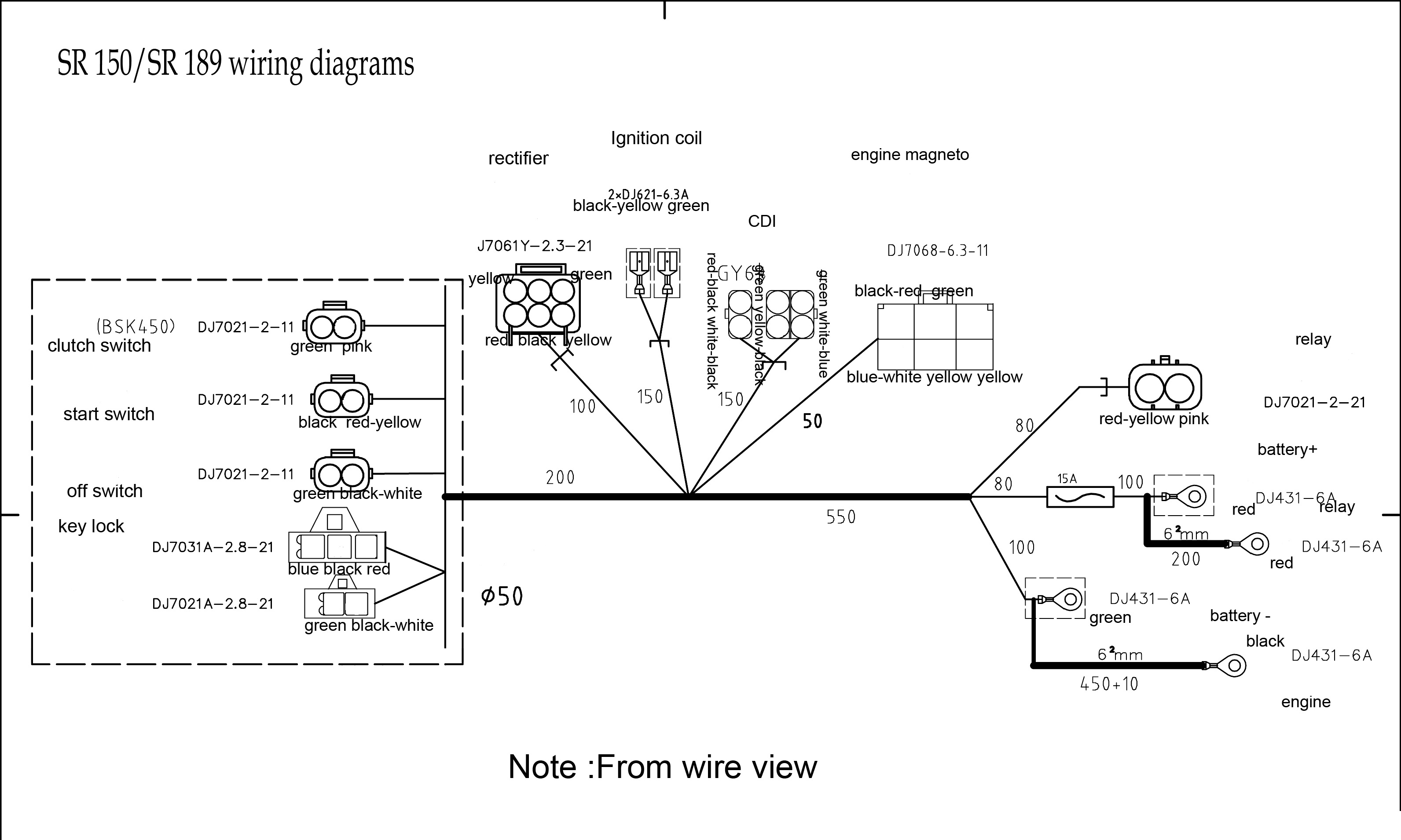
6 Pin Cdi Wiring Diagram | Wiring Diagram from 2020cadillac.com 4 pin trailer wiring diagram. The extra 4 pins were added to the 24 pin version of the cable to provide one extra wire for ground, 3.3, 5, and 12 volts. Wiring / sockets see diagrams on page 75 8 pin octal (see below) functions include: Cut and strip (ground) black wire pin 24 and (+12v) yellow wire pin 11. It shows the components of the circuit as simplified shapes, and the knack and signal links amongst the devices. Modular connector plug and jack pin out. I purchased a 2 pole toggle switch (on/off) and a 4 pin auto relay (30 amp i believe). It shows what sort of electrical wires are interconnected and will also show where fixtures and components may be coupled to the system.
Pinout diagrams and wire colours for cat 5e, cat 6 and cat 7.
Pinout diagrams and wire colours for cat 5e, cat 6 and cat 7. Attach these wires to a compatible connector to power the arduino board (in circuit diagram). Here is a wiring diagram and pin out: 4 pin trailer wiring diagram. Second signal pin to controller pin socket 3 (in circuit diagram). A wiring diagram is an easy visual representation in the physical connections and physical layout of an electrical system or circuit. I purchased a 2 pole toggle switch (on/off) and a 4 pin auto relay (30 amp i believe). The following ecu wiring information is to be used as a guideline only. Black cable serves as floor, exactly like in every other device. It has a 6 pin and a 8 pin. When and how to use a wiring. 6 pin cdi.conection and wiring diagram.(tagalog tutorial) part 3. Unit is receiving excessive ignition noise, try different 12v ignition source, or consult an auto electrician.
Modular connector plug and jack pin out. Wiring / sockets see diagrams on page 75 8 pin octal (see below) functions include: Cut and strip (ground) black wire pin 24 and (+12v) yellow wire pin 11. Each part should be set and linked to different parts in particular manner. Rj45 wiring pinout for crossover and straight through lan ethernet network cables.
6 Pin Trailer Connector Wiring Diagram | Free Wiring Diagram from ricardolevinsmorales.com Each component ought to be placed and connected with other parts in specific manner. Cut and strip (ground) black wire pin 24 and (+12v) yellow wire pin 11. I've attached an image of the wiring according to the diagram you linked with the yellow and black colour. A wiring diagram is an easy visual representation in the physical connections and physical layout of an electrical system or circuit. According to wiring diagram change 6 pin din plug to usb, you will find only four wires used in the cable.typically it uses black, green, red and white wire colours. Each part should be set and linked to different parts in particular manner. There are 2 rows of pins, 3 pins. Even though the keyswitch harness connectors.
The original keyswitch may also create a challenge.
According to wiring diagram change 6 pin din plug to usb, you will find only four wires used in the cable.typically it uses black, green, red and white wire colours. I mounted the lights, but am not sure how to properly wire them up. The red one is to get positive wire with dc power of 5 volts. 4 pin trailer wiring diagram. It shows the components of the circuit as simplified shapes, and the knack and signal links amongst the devices. Here is a wiring diagram and pin out: Attach these wires to a compatible connector to power the arduino board (in circuit diagram). You'll love our internet and hosting services. This type of connector is normally found on utvs, atvs and trailers that do not have their own braking system. N please connect wires correctly and reliably. Start date sep 21, 2018. Basically i'm looking for the wiring diagram for the cable in this picture. Ethernet cable pin outs align the colored wires according to the wiring diagrams above.